An Arc Flash Analysis is a crucial safety assessment designed to identify and mitigate the risks associated with arc flash incidents in electrical systems. An arc flash occurs when a fault in an electrical system causes a high-temperature discharge of energy, resulting in intense heat, pressure waves, and flying debris. Conducting a detailed arc flash analysis helps protect personnel, prevent equipment damage, and ensure compliance with safety standards such as IEEE 1584 and NFPA 70E.
Arc Flash Study
Why is Arc Flash Analysis Important?
- Personnel Safety: Arc flash incidents can cause severe burns, hearing loss, blindness, and even fatalities. A thorough analysis identifies high-risk areas and helps implement appropriate protective measures.
- Regulatory Compliance: Ensuring that your facility meets industry safety standards such as NFPA 70E and OSHA regulations is essential for avoiding legal liabilities and fines.
- Equipment Protection: Arc flash events can damage critical electrical infrastructure, leading to costly repairs and operational downtime. An analysis helps safeguard assets by recommending preventive measures.
- Risk Reduction: Identifying and mitigating arc flash hazards helps reduce the likelihood of unexpected failures and ensures a safer working environment.
Determining Arc Flash Incident Energy: Step-by-Step Guide
First, we must outline the study’s scope and deliverables in accordance with IEEE 1584.1:2022
The procedure to calculate incident energy and define Arc-Flash boundaries, as outlined by IEEE 1584:2018, involves the following steps:
STEP 1: Collect the system and installation data
The typical initial step in an Arc Flash Analysis involves collecting all existing electrical drawings i.e. single line diagram (SLD)available to the client.
In the absence of existing documentation, comprehensive electrical one-line diagrams must be created in the field, requiring a thorough field survey.
STEP 2: Determining the operational modes of the system
Single-line diagrams need to be created or revised to depict the current configuration and operational modes of the power system.
STEP 3: Calculate the bolted fault currents
A short circuit study is essential for assessing the current magnitude circulating within the power system at critical junctures during different time intervals subsequent to a fault event
STEP 4: Establish typical gap and enclosure dimensions based on equipment classes and system voltages
If actual gap measurements from the installed equipment are available, they can be used. Otherwise, it’s necessary to stick to the values provided in the standard
STEP 5: Determine the equipment electrode configuration
Data collection should include information available on-site. For instance, a panel board may contain both VCB and VCBB electrode configurations, while switchgear may have HCB depending on the bus and conductor arrangement.
STEP 6: Establish the working distances
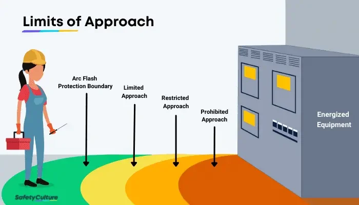
Arc-Flash protection primarily focuses on the incident energy level affecting the head and torso at the designated working distance, rather than that on the hands or arms. Typical working distances are provided in IEEE 1584:2018 based on the equipment class.
STEP 7: Determining the Arcing Current
The total arcing current at a specific location is derived from the total bolted fault current available at that location. This calculated arcing current is usually lower than the bolted fault current due to arc impedance.
STEP 8: Establishing the Arc Duration
The arc duration refers to the period during which the upstream energizing source of arcing current ceases to supply current or energy to the arc fault. Usually, the clearing time of overcurrent protective devices is contingent upon the magnitude and/or direction of the arc current passing through their current sensing equipment (such as current transformers, relays, etc.)
STEP 9: Determine the Incident Energy
Incident energy calculations should be conducted at each switchgear, panel, and distribution board (DB) location defined to ascertain the highest magnitude incident energy or ‘worst-case’ scenario.
STEP 10: Defining Arc-Flash Boundaries Across All Equipment
The Arc-Flash boundary is the distance from a potential Arc Flash source where the incident energy is measured to be 1.2 cal/cm2.
Exploring the Next Steps: What Comes Next?
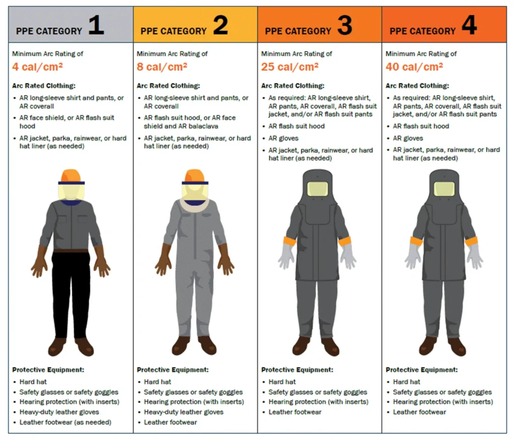
After calculating the incident energy and establishing Arc flash boundaries for all equipment, the study’s final results are important for selecting Arc-rated PPE and clothing with sufficient arc ratings. It is recommended to affix Arc Flash labels on the front side of every panel to ensure worker awareness.
Furthermore, marking the Arc Flash boundary and limited approach boundary in front of every panel, as per IEEE 1584 and NFPA 70E 2021 recommendations, is advisable for safety compliance.
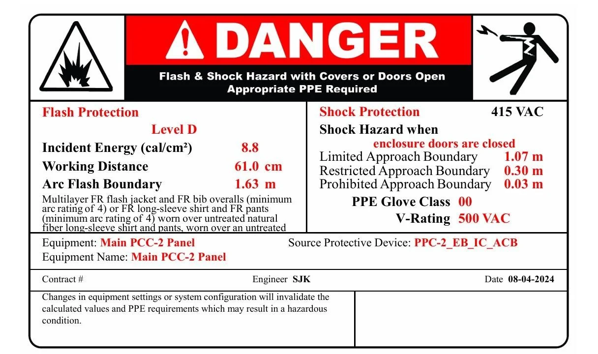
Arc Flash Labels: Ensuring Safety Awareness:
Recommended Practice: Placing Arc Flash Labels on Panels Arc Flash labels should be affixed to the front side of each panel to enhance worker awareness.
These labels provide essential information such as Incident energy level, Working distance, Limited approach boundary, Restricted approach boundary, Arc Flash boundary, and recommended Arc Rated PPE
Outcomes of Arc Flash Analysis
- Incident Energy Calculation: Determines the energy released during an arc flash event to define appropriate personal protective equipment (PPE) requirements.
- Arc Flash Hazard Labels: Provides clear labeling of equipment with hazard levels and PPE guidelines to enhance on-site safety.
- Protective Device Coordination: Optimizes the response of circuit breakers and relays to minimize the duration and severity of arc flash incidents.
- Mitigation Strategies: Recommends engineering and administrative controls, such as improving grounding, adjusting protection settings, and using arc-resistant equipment.
- Compliance Report: Delivers a detailed report covering hazard levels, recommended PPE, and corrective actions to maintain regulatory compliance.

Reference Standards:
- NFPA70E: Standard for electrical safety in the workplace
- IEEE Std 1584: IEEE Guide for performing Arc flash hazard calculation
- IEEE Std 1584.1.2022: IEEE Guide for the specification of Scope and Deliverable Requirement for an Arc-Flash Hazard Calculation Study in accordance with IEEE std 1584