
Arc Flash Study
What is an Arc Flash and Why Does It Matter?
An arc flash is a sudden, explosive release of electrical energy caused by a fault in an energized system. It produces extreme heat, intense pressure waves, blinding light, and flying molten metal. These effects can cause severe burns, hearing loss, vision damage, or even death. Because an arc flash event happens in an instant, there is no time to react once it begins. That is why identifying and managing arc flash hazards in advance is so critical.
At Bigeta Energy Solutions, our Arc Flash Study under the Safety & Reliability service line is designed to protect the people who work on or near electrical equipment every day. The study assesses your facility’s electrical system, identifies where arc flash hazards exist, determines how serious they are, and defines the protective measures needed to keep workers safe.
Why is Arc Flash Study Important?
Worker Protection
Electricians, operators, and maintenance personnel are exposed to arc flash hazards whenever they work on or near energized equipment. Without a formal Arc Flash Study, there is no reliable way to know how dangerous a piece of equipment actually is. The study calculates the incident energy level at each equipment location — measured in cal/cm² — and uses this value to determine the correct arc-rated PPE (Personal Protective Equipment) for that task. This ensures workers are adequately protected, even in a worst-case fault scenario.
Regulatory Compliance
Electrical safety standards such as NFPA 70E (Standard for Electrical Safety in the Workplace), IEEE 1584, and OSHA regulations require employers to assess arc flash hazards and protect workers accordingly. Non-compliance can lead to legal penalties, equipment shutdowns, and serious financial liability — especially after an incident. Our Arc Flash Study delivers a documented, standards-compliant report that demonstrates your organization has met these regulatory obligations.
Creating a Safe Work Culture
When arc flash labels are placed on every panel and workers understand what those labels mean, safety becomes part of daily practice. No one should energize or work on electrical equipment without first checking the arc flash label, confirming required PPE, and establishing approach boundaries. A well-conducted Arc Flash Study lays the foundation for this safe work culture, supported by written electrical safety procedures aligned with NFPA 70E.
How We Conduct the Arc Flash Study
Our study follows the step-by-step procedure defined by IEEE 1584:2018 and scoped as per IEEE 1584.1:2022. Here is how the process works:
Step 1: Field Survey and Data Collection: A comprehensive field survey is conducted to verify electrical system information, inspect critical assets, collect equipment and protection data, and develop or update Single-Line Diagrams (SLDs) as required.
Step 2: Short Circuit Analysis: A detailed short-circuit study is performed to determine the fault current levels throughout the electrical system. Using the IEEE 1584:2018 methodology, arcing currents are calculated and evaluated under both maximum and minimum fault conditions to identify the worst-case incident energy exposure and support accurate arc flash risk assessment.
Step 3: Determining Arc Duration: Arc duration is determined by evaluating the operating time of the protective device responsible for clearing an arcing fault. Time-current characteristic (TCC) curves, relay settings, current transformer ratios, and intentional protection delays are analyzed to establish fault-clearing times, enabling accurate incident energy calculations and identification of arc flash hazards .
Step 4: Incident Energy Calculation:Incident energy levels are calculated for all applicable electrical equipment using the determined arcing current and fault-clearing duration at the specified working distance. Evaluations are performed across all operating scenarios, and the highest incident energy value is used to define arc flash hazards and establish appropriate PPE requirements.
Step 5: Arc Flash Boundary Determination: Arc flash, limited approach, and restricted approach boundaries are calculated to establish safe working distances and shock protection zones, with all values documented on arc flash labels.
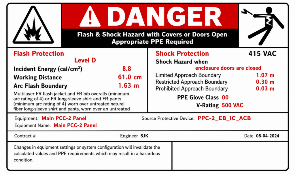
Step 6: PPE Selection and Labeling: PPE requirements are determined based on calculated incident energy levels, and arc flash labels are prepared showing key safety information, including incident energy, working distance, protection boundaries, and minimum PPE requirements.
What Happens When Incident Energy Levels Are Too High?
At some locations, the calculated incident energy may be unacceptably high — making safe work difficult even with the best available PPE. In such cases, we recommend engineering controls to reduce the hazard. These may include adjusting relay time delays to clear faults faster, adding current-limiting fuses to reduce available fault current, installing zone-selective interlocking (ZSI) to speed up protective device operation, or recommending remote racking and remote operation equipment to eliminate the need for personnel to be present near energized switchgear during switching operations.
We do not just report high-risk locations — we work with you to bring incident energy levels down to manageable levels wherever technically feasible.
Study Deliverables
At the conclusion of the Arc Flash Safety Study, Bigeta Energy provides the following:
- Updated Single-Line Diagrams (SLDs): Field-verified electrical drawings showing the current system configuration.
- Arc Flash Incident Energy Report: A detailed table listing incident energy, arc flash boundary, and PPE requirements for every piece of equipment studied.
- Arc Flash Hazard Labels: NFPA 70E 2024 and IEEE 1584 compliant labels ready for installation on each panel.
- PPE Recommendations: Equipment-specific guidance on arc-rated PPE requirements for workers.
- Mitigation Recommendations: Prioritized engineering actions to reduce incident energy levels at high-risk locations.
- Compliance Report: A formal document covering study scope, methodology, standards applied, hazard findings, and corrective actions — suitable for regulatory review and management sign-off.
Applicable Standards
Our Arc Flash Safety Study is conducted in compliance with the following standards:
- NFPA 70E:2024 — Standard for Electrical Safety in the Workplace
- IEEE 1584:2018 — Guide for Performing Arc Flash Hazard Calculations
- IEEE 1584.1:2022 — Guide for Specification of Scope and Deliverable Requirements for an Arc Flash Hazard Calculation Study
When Should You Update Your Arc Flash Study?
- New equipment installation or replacement of transformers, switchgear, or protective devices.
- Changes in the utility fault level or supply configuration.
- Addition of new loads that alter the available fault current.
- Modifications to relay settings or protection coordination.
- After any arc flash incident or near-miss event.
Our Trusted Customers
Bigeta Energy Solutions has conducted Arc Flash Studies across manufacturing plants, data centers, hospitals, commercial buildings, and industrial facilities across India. Our team of certified electrical safety professionals combines strong technical knowledge with hands-on field experience.
We work closely with your electrical and safety teams throughout the study — explaining findings clearly, helping your team understand arc flash labels and PPE requirements, and supporting the implementation of mitigation recommendations. We also offer Electrical Safety Training aligned with NFPA 70E to help your workforce understand arc flash hazards and practice safe work procedures.
Our goal is simple: ensure that every person who works on electrical equipment in your facility has the information, the protection, and the procedures they need to do so safely.
Our Trusted Customers


Partner with Bigeta Energy Solutions
Unlock efficiency, drive sustainability and build a future powered by smarter energy management.