
Arc Flash Analysis
Arc Flash Analysis as Part of Power System Studies
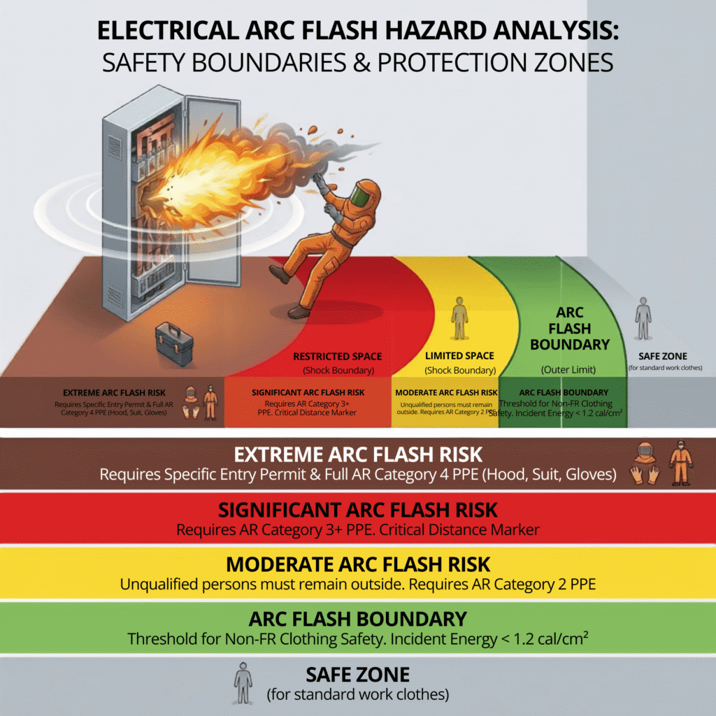
An arc flash is an arcing fault — a fault condition where electrical current flows through ionized air between conductors. The energy released during such an event depends on the available fault current and the time taken by protective devices to clear the fault. Calculating this energy accurately is a core power system engineering task. It requires a properly modeled electrical network, accurate short circuit data, and a thorough understanding of how the protection system responds to faults.
At Bigeta Energy Solutions, the Arc Flash Analysis is offered as part of our Power System Studies service. It is performed alongside short circuit analysis, load flow studies, and relay coordination studies. Together, these studies give engineers a complete picture of the power system’s behavior under both normal and fault conditions. The arc flash Analysis specifically tells us: how much thermal energy is released at each point in the system during an arcing fault, and what needs to be done — in terms of protection settings, equipment selection, and PPE — to manage that hazard.
Arc Flash Hazard Analysis and System Reliability
Short Circuit Study as the Foundation of Arc Flash
Arc flash calculations begin with short circuit analysis. The bolted fault current at each bus or equipment location is calculated first. From this, the arcing current is derived using the IEEE 1584:2018 empirical model. Arcing current is typically lower than bolted fault current because of the impedance introduced by the arc itself. Both maximum and minimum arcing current values must be evaluated, as the worst-case incident energy may occur at either end of the range depending on how the upstream protective device responds.
Load Flow Contribution to Arc Flash Modelling
Load flow analysis determines the operating voltage and current at each point in the system under normal conditions. These values influence transformer loading, tap positions, and the effective source impedance — all of which affect available fault current during an arcing event. A correctly executed load flow study ensures that the fault current inputs used in arc flash calculations reflect realistic operating conditions rather than conservative assumptions.
Role of Protection Systems in Arc Flash Mitigation
The arc duration — the time from fault initiation to fault clearance — is determined by the characteristics of the upstream protective device. This could be a circuit breaker, an overcurrent relay with a current transformer (CT), or a fuse. The clearing time is read from the time-current characteristic (TCC) curve of the protective device, accounting for relay pickup settings, time-dial settings (TDS), and intentional coordination delays. Shorter clearing time means shorter arc duration and lower incident energy. This is why relay coordination directly affects arc flash hazard levels.
Arc Flash Considerations in Equipment Design
Arc flash incident energy levels directly influence equipment selection decisions. Switchgear must be rated to withstand the maximum fault current at its terminals. Beyond that, the arc flash Analysis tells us whether the calculated incident energy is within safe limits for the equipment type and whether arc-resistant switchgear — tested per IEEE C37.20.7 — should be specified. For new installations, arc flash analysis informs the design of bus arrangements, the selection of electrode configurations, and the placement of current-limiting devices.
IEEE 1584:2018 Methodology: Step by Step
Bigeta Energy follows the full ten-step calculation procedure defined by IEEE 1584:2018 and scoped in accordance with IEEE 1584.1:2022. Every step is applied consistently across all equipment in the study scope.
Step 1: System Data Collection and Model Development: Electrical system data, equipment parameters, and protection details are collected and verified to develop an accurate power system model that reflects actual site conditions and serves as the foundation for detailed network analysis.
Step 2: Operational Mode Analysis: Different system operating configurations are evaluated to assess variations in fault current and incident energy levels, ensuring that the worst-case condition is identified for arc flash labeling and PPE determination.
Step 3: Short Circuit Calculation: Maximum fault current levels are calculated across the electrical network to determine system fault duties and provide the basis for subsequent arcing current and arc flash hazard assessments.
Step 4: Electrode Configuration and Enclosure Parameters: specific electrode configurations( VCB,VCBB,HCB) are identified and incorporated into the arc flash model to ensure accurate incident energy calculations in accordance with IEEE 1584:2018 methodology.
Step 5: Working Distance: Standard working distances are assigned based on equipment type and application in accordance with IEEE 1584:2018, ensuring that incident energy calculations accurately represent the exposure levels experienced by personnel during normal operation and maintenance activities.
Step 6: Arcing Current Calculation: Arcing currents are calculated using the IEEE 1584:2018 methodology, capturing the worst-case incident energy condition. This approach accounts for variations in protective device operating times, ensuring a comprehensive and accurate arc flash hazard assessment.
Step 7: Protective Device Clearing Time: Protective device operating characteristics, including relay settings, breaker trip functions, and fuse clearing curves, are analysed to determine fault-clearing times and accurately establish the arc duration used in incident energy calculations.
Step 8: Incident Energy Calculation: Using the calculated arcing current, fault-clearing time, and working distance, incident energy levels are determined for each equipment location, providing a quantitative measure of potential thermal exposure and forming the basis for arc flash risk assessment and PPE selection.
Step 9: Arc Flash Boundary Determination: Arc flash, limited approach, and restricted approach boundaries are calculated for each equipment location to define safe working distances, identify personnel exposure risks, and support compliance with NFPA 70E safety requirements.
Step 10: Results Documentation and Mitigation Analysis: Study findings are documented in a comprehensive engineering report, including detailed results, arc flash hazard assessments, and practical mitigation recommendations to reduce incident energy levels and improve electrical safety.
What Happens When Incident Energy Levels Are Too High?
High incident energy levels are not simply accepted and labelled — they can often be reduced through targeted engineering changes. Bigeta Energy evaluates the following mitigation options as part of the Power System Arc Flash Analysis:
Protective Device Setting Optimization: While reducing the clearing time of upstream relays or enabling instantaneous pickup functions can cut incident energy linearly, doing so blindly can ruin your system’s selectivity. We analyze your protection curves to determine if setting changes are feasible without causing nuisance tripping across adjacent zones.
Zone-Selective Interlocking (ZSI):Implementing technologies like Zone-Selective Interlocking (ZSI) allows circuit breakers to dynamically communicate during a fault. Designing and commissioning a ZSI matrix requires precise engineering to ensure downstream breakers clear faults instantly while upstream devices maintain proper backup coordination.
Current-Limiting Devices: In older facilities where relay adjustments aren’t enough, strategically introducing current-limiting devices can suppress the available fault current. Determining the exact placement and rating of these devices requires rigorous short-circuit modeling.
Arc Flash Detection Relays: For critical high-energy switchgear, conventional overcurrent protection is often too slow. High-speed arc flash detection relays utilize light sensors to initiate a trip in under a cycle. Integrating these optical sensors into existing protection schemes requires specialized design engineering.
Arc-Resistant Switchgear: For new installations or total retrofits, Arc-Resistant Switchgear can be specified. While this doesn’t reduce the energy at the source, it safely redirects blast pressures. Selecting and integrating the right arc-resistant equipment requires a deep understanding of structural and electrical boundaries.
Study Deliverables
Bigeta Energy delivers the following outputs from the Power System Arc Flash Analysis:
- Calibrated Power System Model: A documented, software-based model of the electrical network used for all arc flash, short circuit, and load flow calculations — ready for future updates as the system changes.
- Short Circuit Analysis Results: Fault current values at all study nodes, including maximum and minimum symmetrical fault currents and asymmetrical peak values.
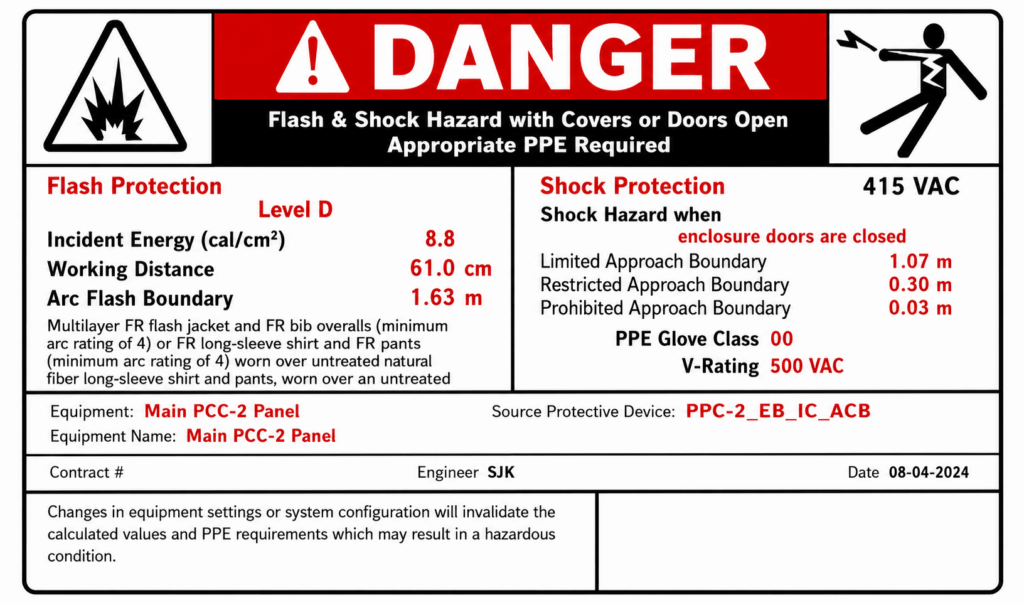
- Arc Flash Incident Energy Report: A comprehensive table showing calculated incident energy, arc flash boundary, working distance, and PPE arc rating requirements for every equipment location, for all operational modes studied.
- Protective Device Coordination Summary: Documentation of the clearing times and TCC curves used in arc flash calculations, with recommendations for setting changes where beneficial.
- Mitigation Engineering Report: Quantitative analysis of recommended engineering interventions, with before-and-after incident energy comparisons to show the effect of each proposed change.
- Updated Single-Line Diagrams: Revised, field-verified SLDs reflecting current system configuration and annotated with arc flash hazard levels at key nodes.
- Arc Flash Hazard Labels: IEEE 1584 and NFPA 70E 2024 compliant equipment labels containing incident energy, working distance, arc flash boundary, approach boundaries, and required PPE arc rating.
Standards and References
Our Power System Arc Flash Analysis is conducted in accordance with the following standards:
- IEEE 1584:2018 — Guide for Performing Arc Flash Hazard Calculations: the primary calculation standard.
- IEEE 1584.1:2022 — Guide for Specification of Scope and Deliverable Requirements for an Arc Flash Hazard Calculation Study.
- IEEE 242 (Buff Book) — Recommended Practice for Protection and Coordination of Industrial and Commercial Power Systems.
- NFPA 70E:2024 — Standard for Electrical Safety in the Workplace: used for PPE category determination and boundary definitions.
Standards and References
Arc flash analysis is most accurate and most useful when it is performed as part of an integrated power system study. The quality of arc flash results depends directly on the accuracy of the short circuit model and the correctness of protection settings. If these inputs are wrong, the calculated incident energy levels will be wrong — leading either to under-protection (a safety risk) or over-protection (an unnecessary cost burden).
Bigeta Energy conducts all power system studies using a single, consistent network model. This means the short circuit data, load flow results, and relay coordination findings used in the arc flash Analysis are all derived from the same validated model. This eliminates errors and inconsistencies, and it allows us to identify cross-cutting optimization opportunities — for example, a relay setting change that simultaneously improves coordination selectivity and reduces arc flash incident energy at a critical equipment location.
Whether you need a standalone arc flash Analysis or a full power system study package, Bigeta Energy has the engineering expertise to deliver technically sound, actionable results.
Our Trusted Customers


Partner with Bigeta Energy Solutions
Unlock efficiency, drive sustainability and build a future powered by smarter energy management.